The Memory Map of an ATmega328P
To program the bootloader and provide to the microcontroller the compatibility with the Arduino Software (IDE) you need to use an In-circuit Serial Programmer (ISP) that is the device that connects to a specific set of pins of the microcontroller to perform the programming of the whole flash memory of the microcontroller, bootloader included. The ISP programming procedure also includes the writing of fuses: a special set of bits that define how the microcontroller works under specific circumstances.
Use Arduino as ISP
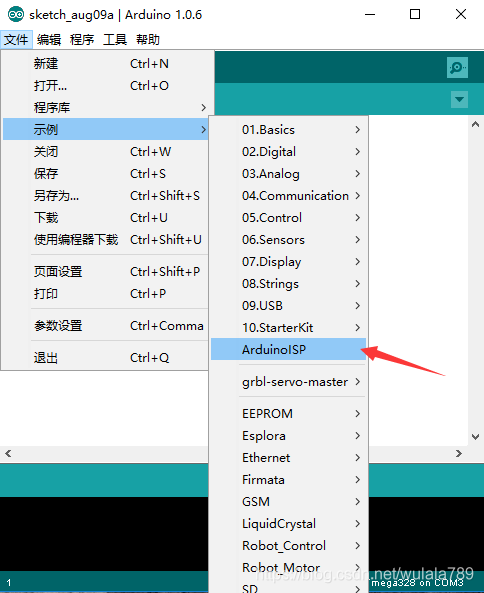
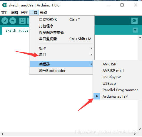
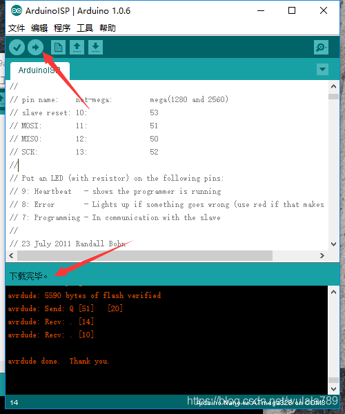
The whole process of loading the bootloader code and burning properly the fuses to make an ATmega microcontroller an "Arduino" is managed by the Arduino Software (IDE): it provides a specific menu item and allows you to use a variety of programming devices. Among the programmers, the "Arduino as ISP" is the cheapest and most practical solution to burn a bootloader on another Arduino board with ATmega, 32U4 or ATtiny.
ATmega328P的内存映射
要对引导加载程序进行编程并向微控制器提供与Arduino软件(IDE)的兼容性,您需要使用一个在线串行编程器(ISP),它是连接到微控制器特定引脚集的设备,以执行微控制器的整个闪存(包括引导加载程序)的编程。ISP编程程序还包括编写保险丝:一组特殊的位,定义微控制器在特定环境下如何工作。
使用Arduino作为ISP
加载引导程序代码和正确烧保险丝以使ATmega微控制器成为“Arduino”的整个过程由Arduino软件(IDE)管理:它提供了一个特定的菜单项,并允许您使用各种编程设备。在程序员中,“Arduino作为ISP”是在另一个Arduino板上使用ATmega、32U4或Attini烧录引导程序的最便宜和最实用的解决方案。
The programming process uses VCC, GND and four data pins. Three pins connect MISO, MOSI and SCK between the programming micro and the target micro, the fourth pin from the programming micro goes to the reset pin of the target.
How to wire your boards
The following table display on which pins the MOSI, MISO and SCK are broken out on the different Arduino boards:
编程过程使用VCC、GND和四个数据引脚。三个引脚将MISO、MOSI和SCK连接在编程微处理器和目标微处理器之间,来自编程微处理器的第四个引脚连接到目标微处理器的复位引脚。
如何给你的电路板布线
The SPI interface - and therefore these pins - is the interface used to program the AVR microcontrollers. Note that MISO, MOSI, and SCK are available in a consistent physical location on the ICSP header; this connector is used also by shields that rely on the SPI interface allowing the design of shields that work on every board.
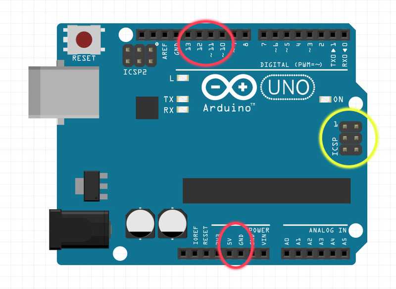
On the Arduino UNO in the following image, we have highlighted in red the connections on the female strips; in yellow the ICSP connector that connects to the ATmega328P. Please note that the Rev.3 board has an ATMega 16U2 chip that manages the USB connection and also that chip can be reprogrammed via a dedicated connector labeled ICSP2, just above the ATMega 16U2 itself.

SPI接口-因此这些引脚-是用于编程AVR微控制器的接口。请注意,MISO、MOSI和SCK在ICSP报头上的一致物理位置可用;此连接器也由依赖SPI接口的屏蔽使用,允许设计在每个板上工作的屏蔽。
在下图中的Arduino UNO上,我们用红色突出显示了母带上的连接;黄色突出显示了连接到ATmega328P的ICSP连接器。请注意,Rev.3主板有一个ATMega 16U2芯片,可以管理USB连接,也可以通过上面标记为ICSP2的专用连接器对芯片进行重新编程atmega16u2本身。
Uno Connect
On some Arduino boards (see table above), pins MOSI, MISO and SCK are the same pins as digital pin 11, 12 and 13, respectively. That is why many tutorials instruct you to hook up the target to these pins. If you find this wiring more practical, have a define USE_OLD_STYLE_WIRING. This will work even when not using an Uno. (With the Uno board this is not needed).
在某些Arduino板上(见上表),管脚MOSI、MISO和SCK分别与数字管脚11、12和13相同。这就是为什么许多教程都会指导您将目标连接到这些管脚上。如果您觉得这种接线更实用,请定义使用旧型接线。即使不使用Uno,这也可以工作。(Uno board 不需要这样做)。
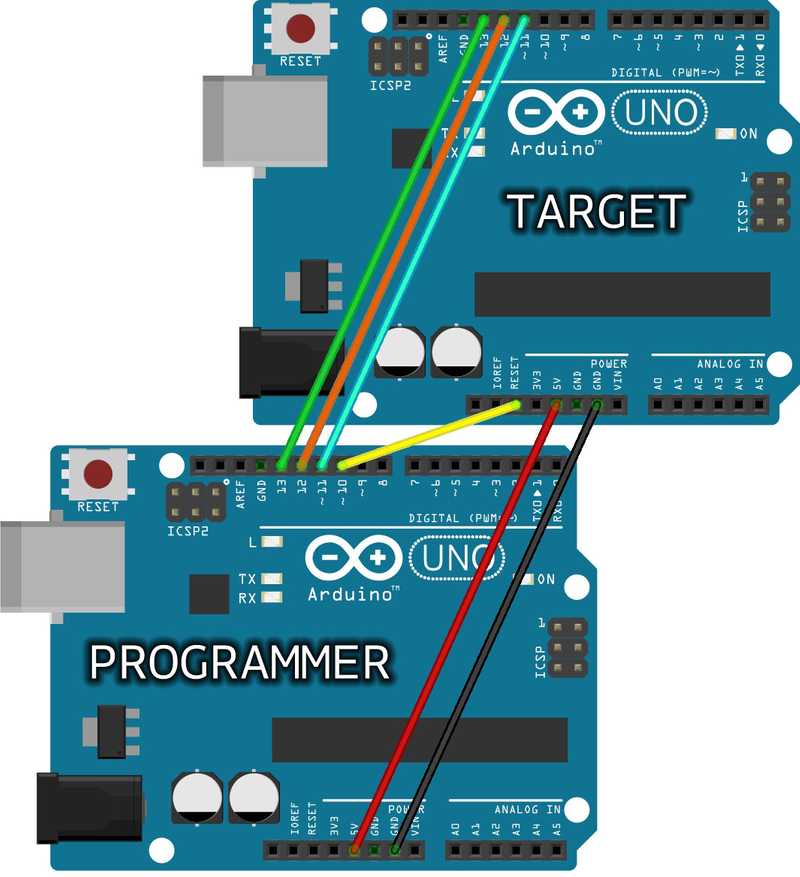
ArduinoUNOtoUNO ISP2
In the picture above we are connecting two UNO boards for bootloader burning with the "old style" connections: the top board is the Target, the bottom board is the Programmer. Note the yellow connection from D10 of the programmer to RESET of the target. On MKR family of boards, you can't use D10 for reset; we suggest D6 and you must remember to change the line 73 of the ArduinoISP sketch - #define RESET 10 - putting "6" insteat of 10.
Arduino ISP wires
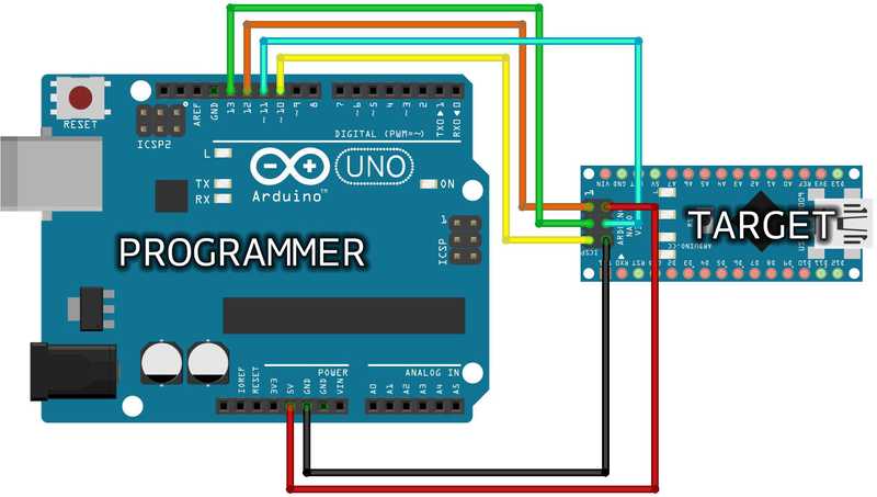
This Arduino NANO is programmed through its ICSP connector with wires coming from D10-D13 of the programmer UNO board.
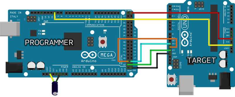
Arduino MEGA To Arduino UNO
The Arduino MEGA above is programming an Arduino UNO connecting D51-D11, D50-D12, D52-D13, GND-GND, 5V-5V and D10 to RESET. This type of board needs a 10µF electrolytic capacitor connected to RESET and GND with the positive (long leg) connected to RESET. The capacitor has to be placed after the programmer board has been loaded with the ISP sketch.
The 10µF electrolytic capacitor connected to RESET and GND of the programming board is needed only for the boards that have an interface between the microcontroller and the computer's USB, like Mega, Uno, Mini, Nano. Boards like Leonardo, Esplora and Micro, with the USB directly managed by the microcontroller, don't need the capacitor.
About voltages
The Arduino family of boards includes 5V and 3.3V devices. When using an Arduino that is not 5V tolerant (Due, Zero, ...) as the programmer, make sure to not expose any of the programmer's pins to 5V. A simple way to accomplish this is to power the complete system (programmer and target) at 3V3.
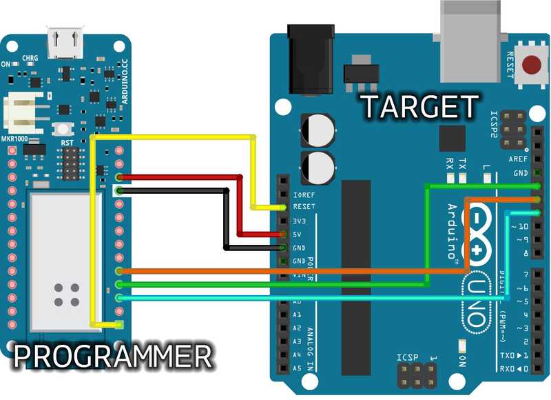
MKR1000 ISP UNO 2
In the above picture you see the wiring between a MKR1000 and a UNO. As described above, everything runs on 3.3V, taken from VCC and GND of the MKR1000 and sent to 5V and GND of the UNO. The same connection could be made to the ICSP of the UNO following the pinout explained in the page. We have used the same colors for the wires as in the other pictures to help you switch from the "old wiring" to the ICSP connector with ease. Please note that the MKR family of boards share the same pinout, therefore you can use any MKR board as ISP programmer. If you use a MKR board as ISP programmer, remember to change the line 73 of the ArduinoISP defining the actual pin used on the MKR board to Reset the target (6 in the picture above).
